


TTL (through the lens) metering is a powerful tool in underwater photography, particularly for macro, close focus wide angle, and especially when shooting a fast moving subject. TTL strobe exposure helps you to get the most out of your dive by maximizing battery life, minimizing time between shots, and producing the most properly exposed shots possible.
Some people call TTL "automatic" exposure but it's not the same as putting your camera on autopilot. On mirrorless and DSLR cameras, TTL strobe metering is available in all camera modes including Manual.
Camera Settings
Some camera settings can change the behavior of or sometimes completely prevent the firing of an external flash. Whenever you're experiencing TTL or flash firing issues, restoring your camera to default factory settings and then applying the settings below is the first step to correcting the problem.
| Canon |
|
| Nikon |
|
|
Olympus Panasonic |
|
|
Sony |
|

(left) Nikon's 1/320 (Auto FP) and (right) Sony ISO Auto Multi Frame NR are examples of settings that can prevent a TTL flash from operating properly with your system.
Data interruption can also prevent a flash from firing correctly. If you're experiencing trouble getting a flash to fire in TTL (or at all), we recommend removing and reinstalling the camera's lens, battery pack, and memory card. Turning your strobes off and back on will also reset data communication to the TTL converter.
Strobe Requirements
All DS160 and DS161 strobes are compatible with all Ikelite TTL systems to date. Older DS strobes may not be able to support newer TTL protocols. Make sure your strobe's serial number is a number higher than that listed in the table below for proper TTL operation.
| Serial # | |
| DS50 | 75510 with update |
| DS51 | 78700 |
| DS125 | 7928 |
| DS200 | 7163 |

The serial number positions are emphasized in these photos. The actual numbers are engraved or stamped onto the strobe body.
Non-DS strobes (typically black or orange) are not compatible with newer digital TTL systems and are incapable of powering a TTL converter. These strobes may be used with some housings in manual power settings.
Weak batteries or a single dead cell can affect strobe operation and exposure. If your strobe uses AA batteries, insert brand new batteries. If using a rechargeable battery, make sure the battery is at least 50% charged.
Hotshoe Connectors
Most housings ship with a manual flash hotshoe. These hotshoes only have two connectors: trigger and ground. The strobe(s) are not receiving TTL data from the camera and should be set in a manual power setting.
When using an external TTL converter like a DS Link (DL1 for Nikon, DL2 for Sony, DL3 for Olympus and Panasonic, DL4 for Fujifilm, DL5 for Canon, etc), it is necessary to have a TTL hotshoe installed in the housing. Our TTL hotshoes are indicated by a yellow band when they are customer installed.
Caution on Using TTL Hotshoes
A TTL hotshoe should not be used without an in-line TTL converter, as power would be applied to the camera from the strobe which may cause damage to the camera's circuitry. When you remove the manual hotshoe from a housing to install a TTL hotshoe, we recommend keeping the manual hotshoe with your spare parts during travel. This way you have a backup if anything should unexpectedly go wrong.

Even a small gap as shown in the image on the left can prevent proper strobe operation. Make sure that the hotshoe is pushed all of the way forward after you install the camera in the housing and before you attach the housing back.
Installing the Hotshoe
The housing's hotshoe attaches to the flash hotshoe mount on the top of the camera. It provides connection to send signals between the camera and the TTL Converter. The hotshoe must be pushed all of the way forward to make good connection with the contacts on the camera and provide TTL operation.

Don't overlook the obvious. Your strobes should be set to TTL when you're setting up and doing testing. Manual power settings only work correctly on the strobes when your converter is switched to manual mode.
Strobe Settings
In a hurry to set up equipment we sometimes miss the "obvious" which is that strobes should be set to TTL when using a TTL converter in TTL mode.
To shoot manual, switch your TTL converter over to manual mode before changing the settings on your strobe. If the converter is left in TTL mode you will not be able to use the full power output of the strobes. Some amount of the flash will be unusable as the strobe will fire on the preflash and only a portion of the flash duration will still be occuring when the actual photo is captured.

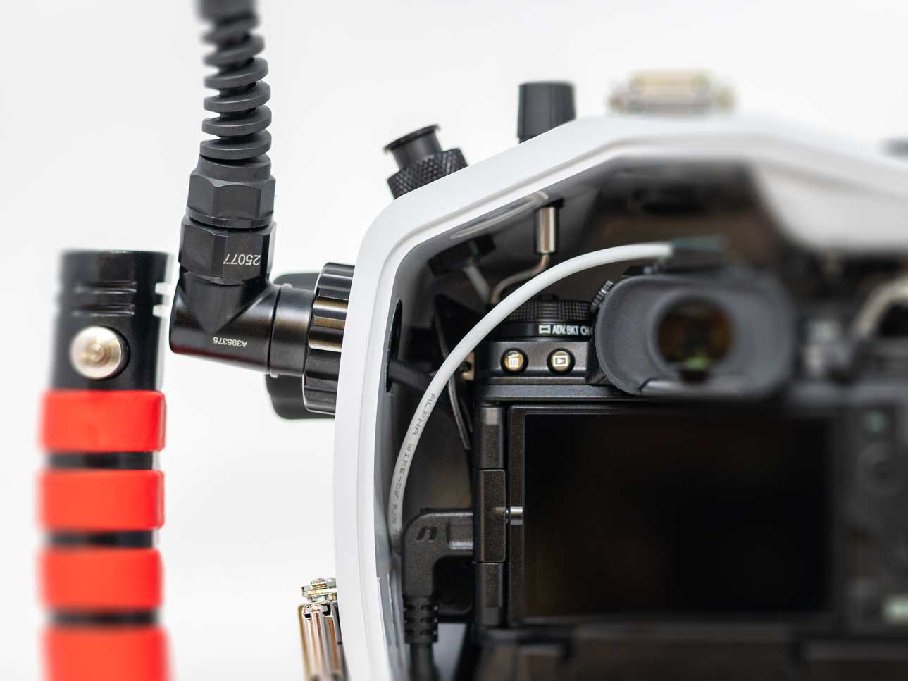
Extra care is required in cases like this where the strobe bulkhead is nickel plated brass (silver in color) and the sync cord plug is type 3 anodized aluminum (black in color). These connectors should be disconnected and cleaned well after each day of diving to avoid seizing up. Even better, consider sending your strobes in to have the bulkheads updated (DS50/DS51 and DS160/DS161 only).
Bulkhead and Plug Connectors
The external flash connection on the housing and strobes is called the "bulkhead." The ends of the cords are referred to as "plugs."
When connecting your system ensure that all of the connector pins and receptacles are clean and bright gold in coloring. The gold contacts become dull and sometimes brownish if they have been exposed to moisture. This can cause intermittent TTL operation.
Line up the plug with the bulkhead and push it all of the way in. You should feel the plug o-ring seat as it pushes into the body of the bulkhead. Thread the retaining ring all of the way down until it won't spin anymore.

Connector contacts should be bright, shiny gold like the plug on the far left. The plug and bulkheads to the right all have signs of water damage as evidenced by the dulling of the gold contacts. This type of damage will cause intermittent strobe functioning.
Connector Maintenance
We recommend detaching, cleaning, and lightly lubricating your cord connectors on a regular basis. If you are using dissimilar metals (a combination of older, nickel plated brass and newer, black anodized aluminum) then the plug ends should be disconnected and cleaned after each day of diving.
It is not necessary to remove the plug o-ring to maintain it. Wipe it completely clean with your finger or a lint-free cloth. Do not use a facial tissue or paper towel which will leave fibers on the o-ring. Put a very small dab of lube on the tip of your index finger and run it around the outside of the o-ring and on the threads of the plug and bulkhead. Do not get lubricant in the center of the plug or bulkhead. Lubricant in the contacts will cause shorting and intermittent strobe operation.

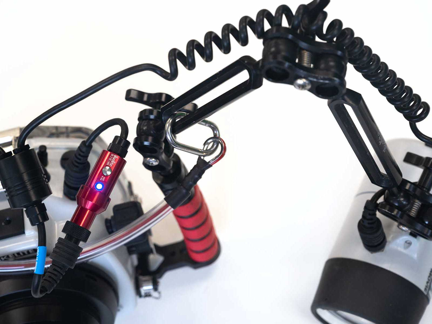
Once your system is turned on a DS Link TTL Converter glows blue to indicate that it is in TTL mode. Pressing the button on the side of the converter toggles back and forth between TTL and manual strobe exposure. When the light is blue, strobes should be set to "TTL". When the light is red, strobes should be set to a manual power setting using the knobs on the sides of the strobes.

Most cameras' LCD displays will show a flash symbol when a TTL flash is attached, but not always. For example on the Canon EOS R6 the flash symbol only shows when the camera is actively metering for a few seconds after the shutter is half-depressed.
Testing TTL Operation
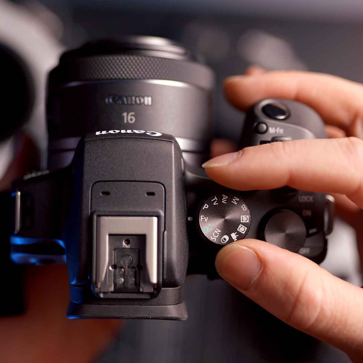
- If using a DL5 DS Link TTL Converter for Canon, check that the converter is on the correct program number based on the camera model you are using. If not, reprogram as necessary.
- Check your connections.
- Check the hotshoe.
- Turn the strobes on.
- Set the strobes to TTL.
- Make sure the TTL converter indicator light is blue (DS Link Converters and newer model Canon SL-series housings only).
- Turn the camera on.
- Set the camera to Aperture priority (A or Av) with aperture set to f/8.
- Point the strobes away from the camera - not in the frame - and point the camera at a dark subject like the underside of a desk. Watch the strobes while you take a photo. The strobes should fire at or near full power and may emit a whining noise as the flash capacitors recharge.
- Point the strobes toward the camera's lens. Watch the strobes while you take a photo. The strobes should fire only a small amount. The ready lights on the strobes should briefly change from red to green.
- Change to Manual (M) mode on your camera and set the shutter speed to 1/1200. Take a photo and watch the shutter speed. It should automatically reduce to 1/200 or 1/250 when taking the photo depending on the camera.
Evaluating the Results
To verify TTL operation, you should be looking for a change in output between the shots in steps 9 and 10. Do not be distracted by exposure information when testing TTL. If the strobe's flash intensity varies, then the strobe is receiving TTL communication from the camera.
Exposure problems are related to camera settings, strobe positioning, and often the lack of a subject for the strobe to expose. If you're testing by taking photos of a room, your strobes will only expose subjects within the range of the strobes. Typically over- or under-exposure problems over frame are due to the fact that your camera settings need to be adjusted for ambient light.

Don't overcomplicate your topside TTL testing. Two shots: one with the strobes pointed away from the camera and one with the strobes pointed towards the lens will tell you whether the TTL is functioning correctly. If the strobe output changes from bright flashes to small blips of light then you're good to go.
Test Firing a Strobe

Using a paperclip to connect the ground and trigger pins on a strobe bulkhead will cause the strobe to fire. If a strobe is capable of repeated firing through its bulkhead but not when connected to a system, the problem is not with the strobe. The problem is somewhere else in your system.
Testing a Sync Cord
 When you have a sync cord attached to the strobe, connecting ground to trigger receptacles on the sync cord should cause the strobe to fire.
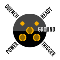
You can test continuity on a sync cord using these wiring diagrams and a multimeter. If testing a dual sync cord, only the Ground, Trigger, and Quench contacts are connected on the coiled cord with a red band.
Additional Reading
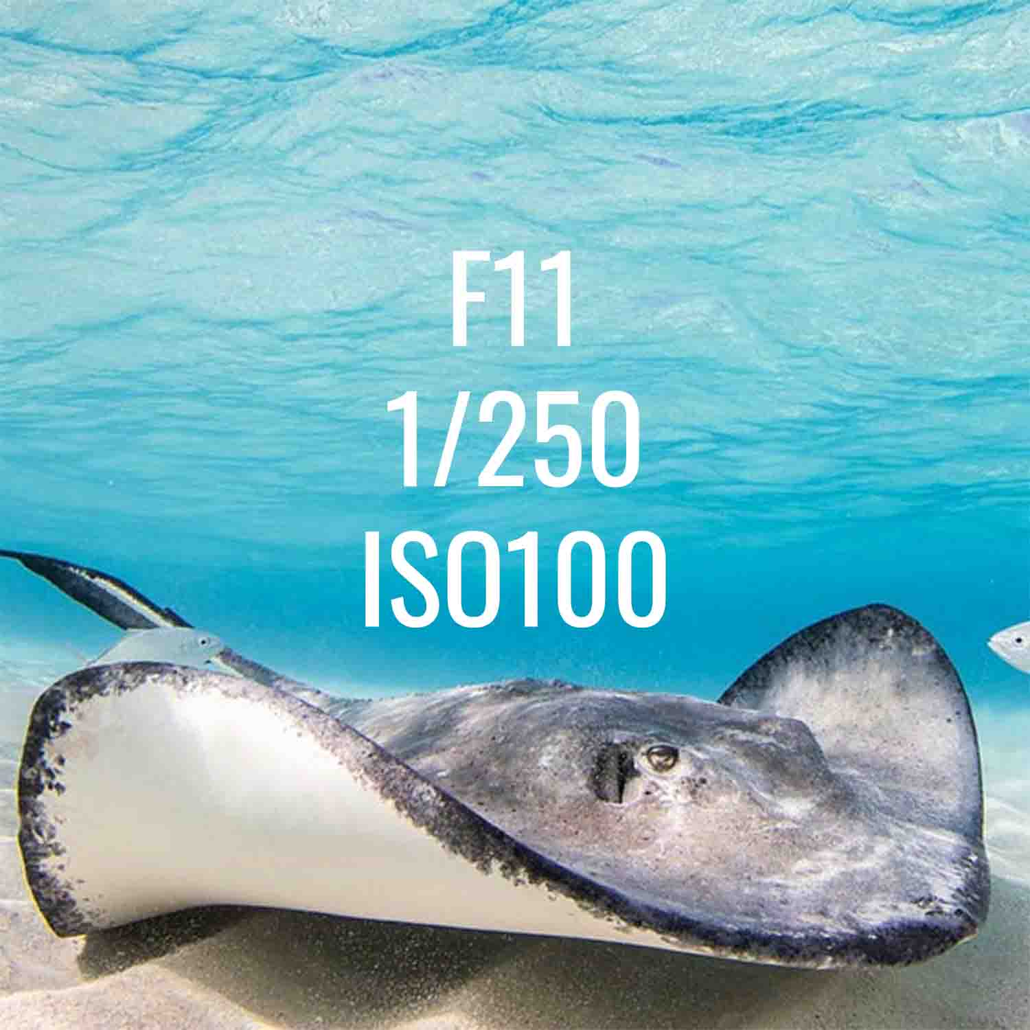
When to Change Aperture Underwater
When to Change Shutter Speed Underwater
Bulkhead + Sync Cord Plug Material Change
The Myth of TTL Strobe Exposure Underwater
Why You Need Strobes Underwater